


I thought to write these notes on a topic that is mostly neglected or not always well highlighted: ground connection. Please look at the follow schema about an easy SE tube amplifier:
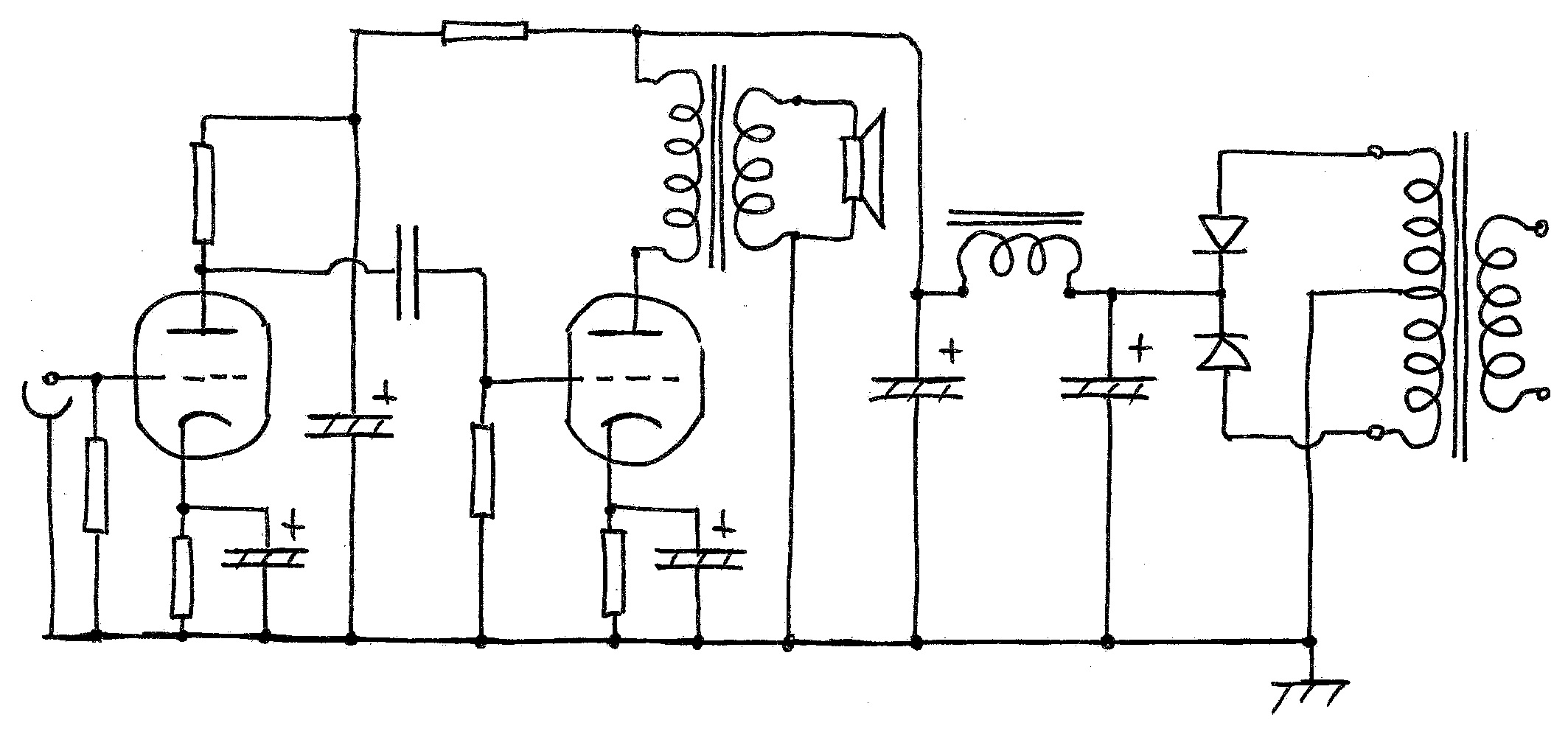
We see a long ground wire and and a connection to metal chassis. But the question is: how is this connection made in practice? after many years of tests in audio devices I can assure you that this topic is very, very important to obtain quiet electronic equipment , increase detail, micro dynamics and definition. Please, observe the redrawn same previous schema:
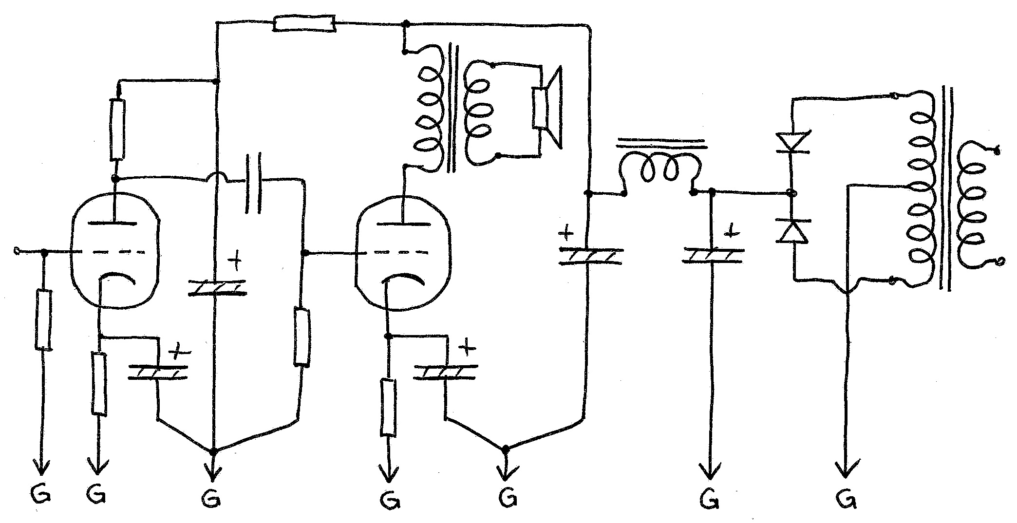
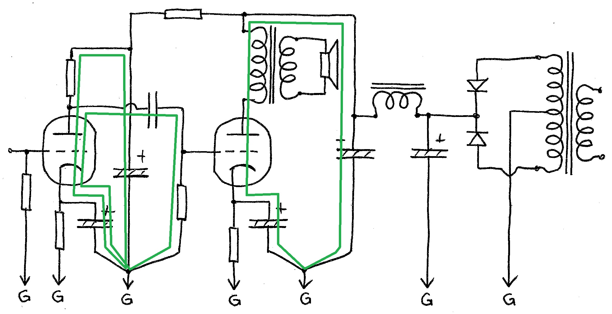
As you can see all the components, resistors and capacitors that enclose the same signal path are connected together and then to the ground bus with a single wire. Why this ? perhaps it will be better understood by looking at the following two schemas with the two paths, signal ( green ) and DC bias ( red ) ways highlighted.
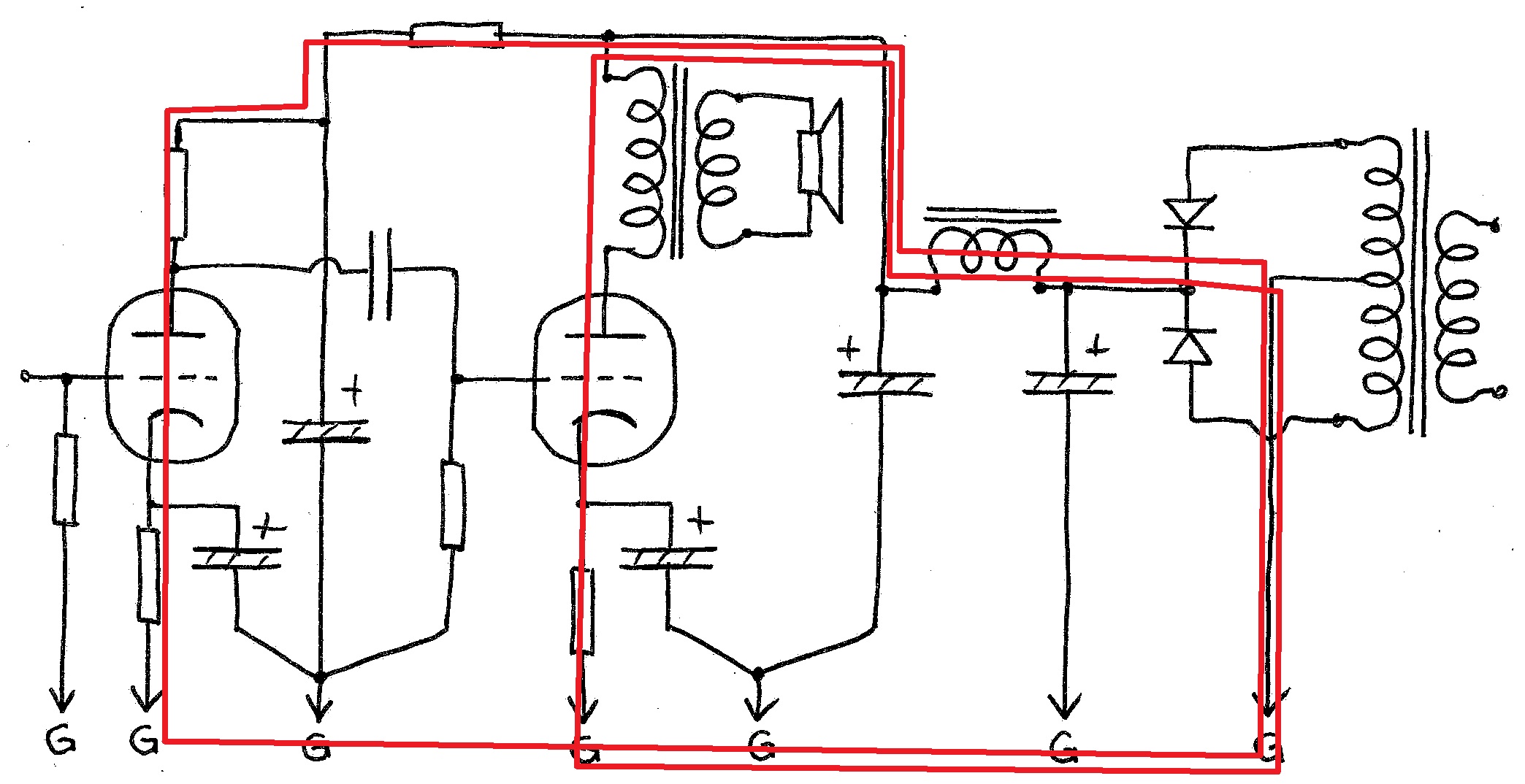
Ground bus consists of a 1.5-2.0 mm diameter bare copper wire insulated from metal chassis ( please see the photos below ). All connections G then belong to this ground bus.
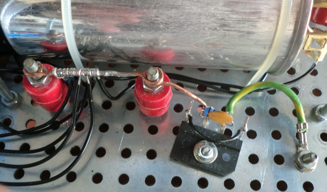
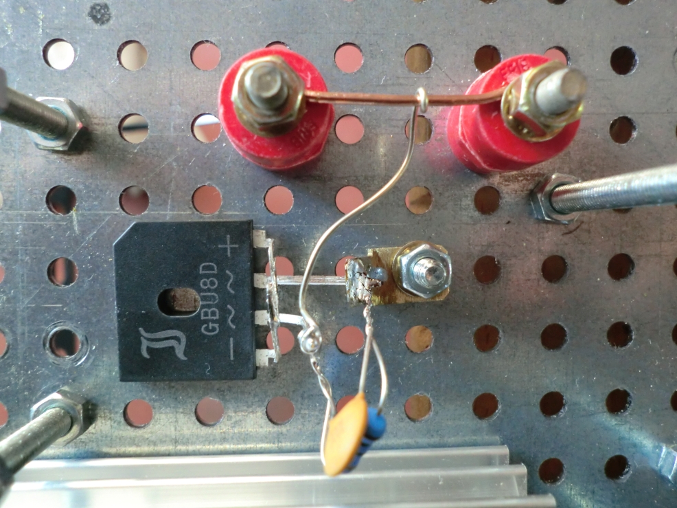
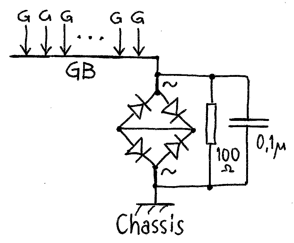
This ground bus GB then is connected to metal chassis via a bridge rectifier ( any 3-10 Amp or more type is OK ) and a 10 Ω 2W resistor with a 0.1 µF ceramic capacitor in parallel to ensure a high frequency noise path to ground. The diode bridge only connect the two ( signal ) and ( chassis ) grount when the voltage difference between them exceeds +/- 1.4V.
And now….excuse me…….

Be First to Comment