

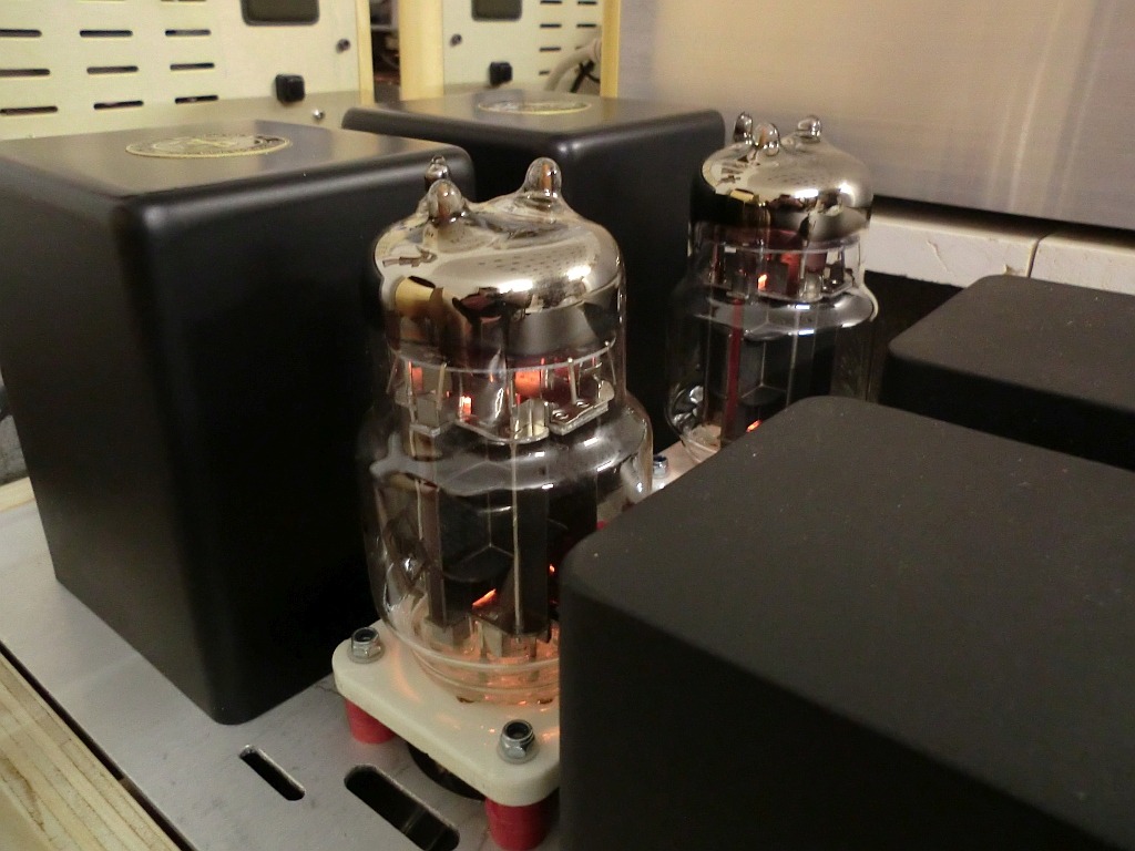
The 6C33C-b is an attractive tube. This indirectly heated, high transconductance, high current capability and low internal resistance, inexpensive triode, from Russia, with a large 60W anode dissipation, originally designed as a voltage regulator for the avionics in Russian military aircraft, it is the ideal “high current” triode for audio applications.
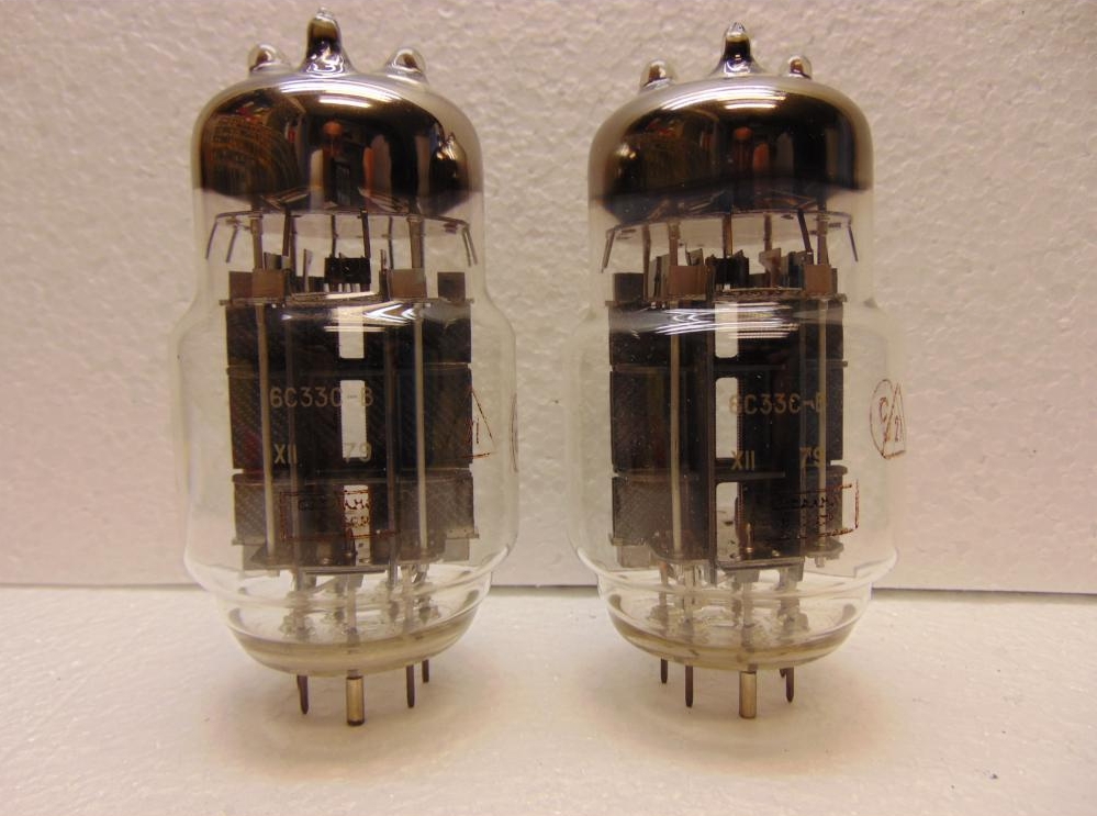
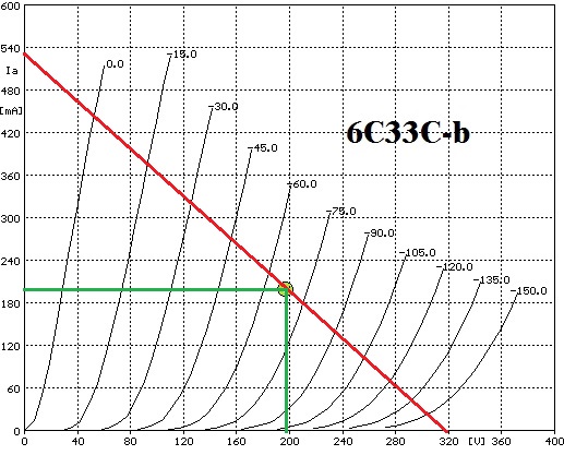
The downside? The 6C33C-B requires a relatively high anode current (typically 180-220mA at 180-210V) a high heater current ( 3,6 A with filaments connect in series or 7,2 A with parallel connection). For this reason the tube runs very hot ( 250-300°C ) and a ceramic socket and adequate ventilation are required. My choice in this project is to use this tube in SE ( Single Ended ) Class A configuration without negative feedback. Due to relatively 6C33C-b low plate resistance, with a 600 Ohm primary impedance output transformer we can obtain 15 W rms at 200 V anode voltage and 200mA of plate current ( 40 W anode dissipation is a good safer choice for a 60 W max tube ). To adopt a 600 ohm output transformer with a very low turns ratio and, as a consequence, extended frequency decade factor (as compared even to the most advanced modern vacuum tube amplifiers), as well as dramatically reduced leakage inductance.
The 6C33C-b needs a very large voltage swing at the grid input to produce 15 Wrms at output side. It’s very important the choice of input/driver tube type and configuration for best sound. I spent two months for testing various front-end tubes and topologies:
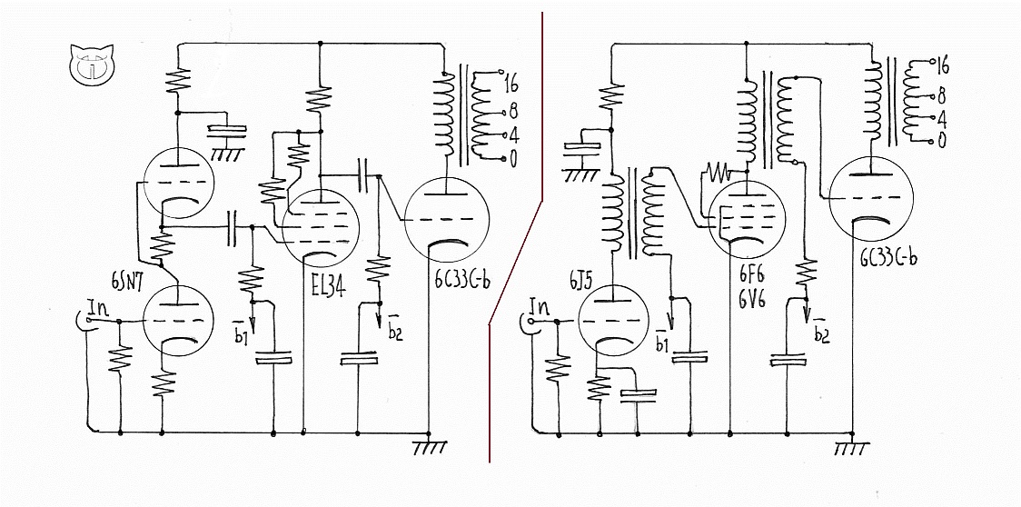
At last my choice was for the circuit below:
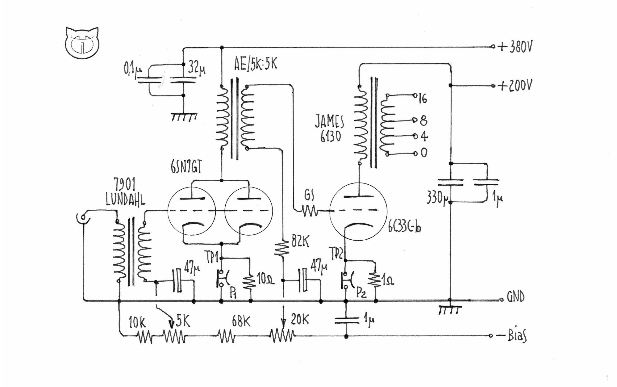
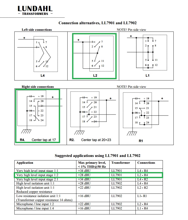
It’s very simple with a very short signal path but with outstanding performance. The Lundahl LL9201 input transformers, offers a galvanic isolation from the upstream stage, a signal gain ( due to 1:2 configuration ) and lastly but not last it allows to adopt a fixed bias per the 6SN7GT. I love this old double triode due her exceptional linearity and sound. Each triode has a raw amplification factor of 20 at a moderately low plate resistance of about 7,7 KOhms.
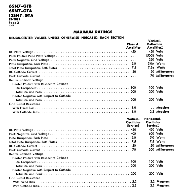
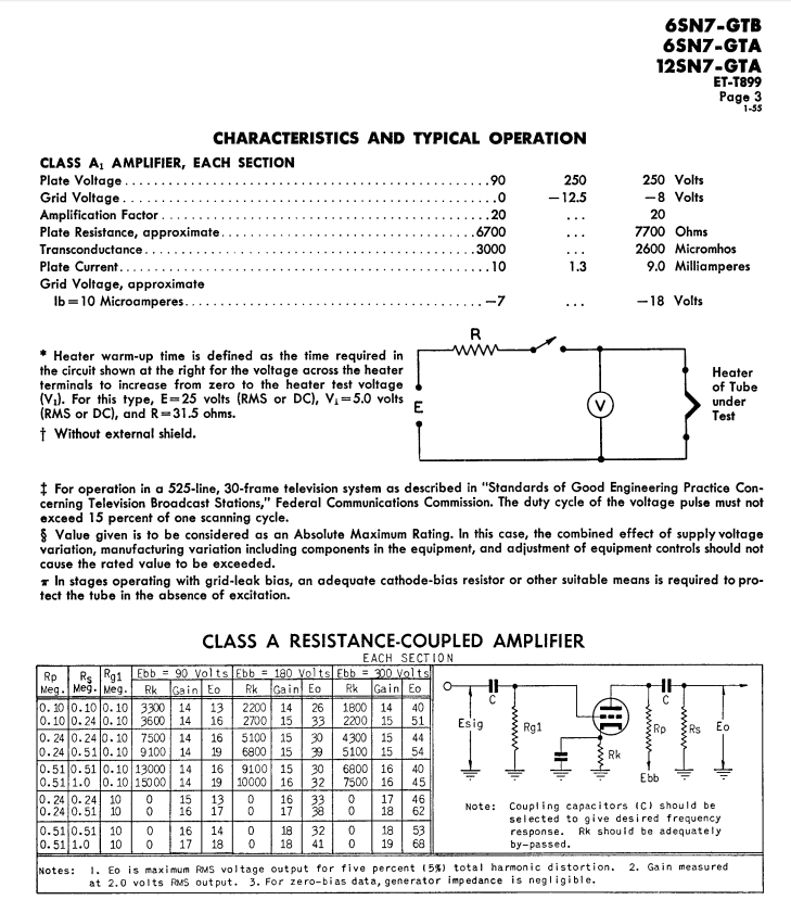
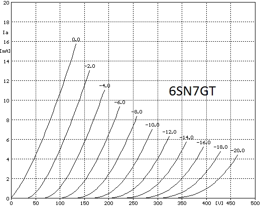
I remember this valve in the famous Williamson Amplifier the first true hi-fi design. I try this tube with both triode in parallel. In this configuration the plate resistance halves ( 3,85 KOhm ), a must for transformer load to obtain the best low frequency response. As interstage transformer I use a custom made 1:1 from AE Europe, 5 Kohm on both sides, 50H (nominal ) of primary inductance ( http://www.aetransformatoren.nl ). 6SN7GT( paralleled ) plus AE transformer, driven under a 15mA current ( 7,5 mA per triode ) at 380 V anode voltage, provide an impressive set of performance: up to 50Vrms ( 140Vp-p ) of output voltage with a very low harmonic distorsion, wide flat bandwith. This stage is perfect to drive a tank-tube as 6C33C-b.
![]()
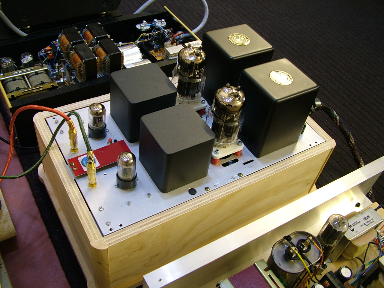
The output transformer is the beautiful, heavy ( 5,2Kg ) James JS-6130 HF. It is rated for 30 W power output with a primary DC current max of 250mA. Primary impedance is 600 Ohm and 3,26 H of inductance. Bandwith at -3dB is extended from 14,3 Hz to 148Khz.

![]()
![]()
![]()
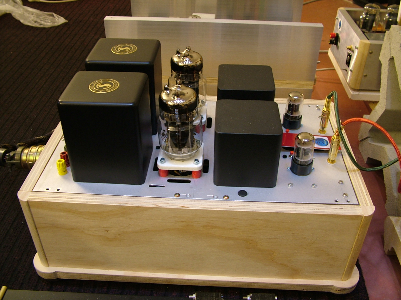
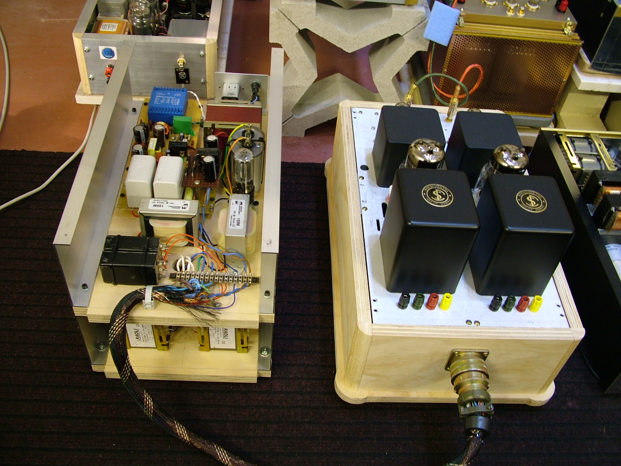
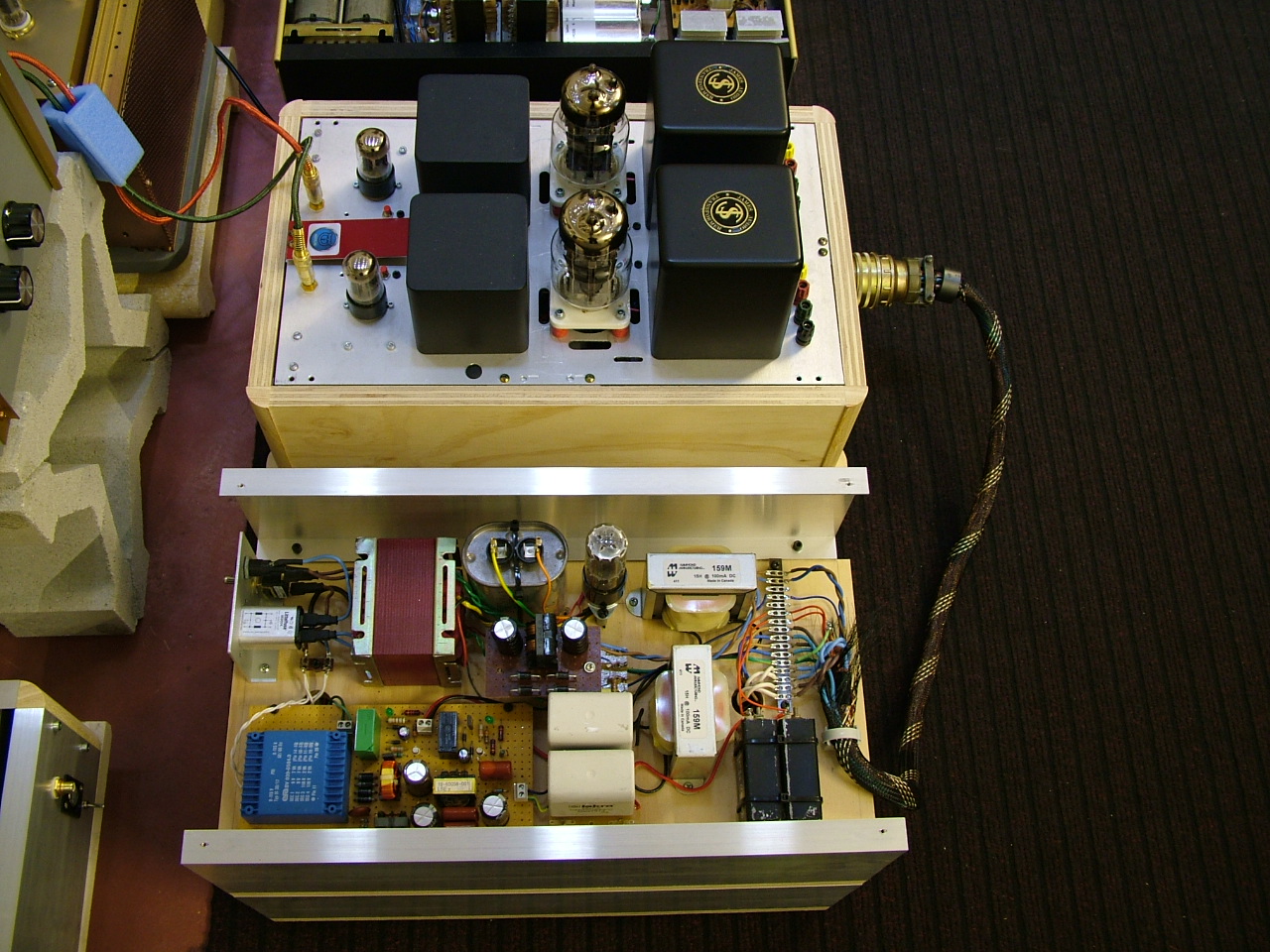
If made in a single chassis this amplifier will be very heavy due to many transformers and choke. This raises two choices: two mono amplifiers or separate power supply from the amplifier chassis. I adopt this last layout because I only have one power transformer for input stage and one for 6C33C-b output stage. Power supply and amplifier it joined with a big military type connector. Please note the last big MKP 330uF reservoir capacitor in the 6C33cb power supply is put in the amp chassis very close to output transformer. Also 33uF MKP capacitor is put very close to interstage transformer and 6SN7.
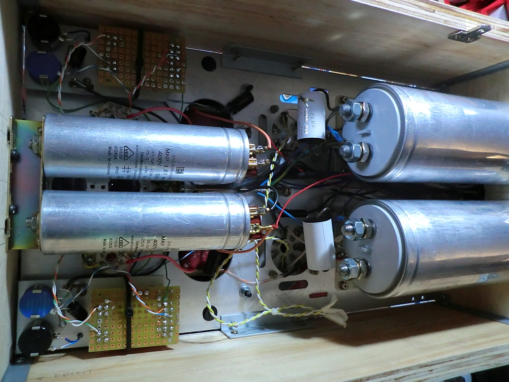
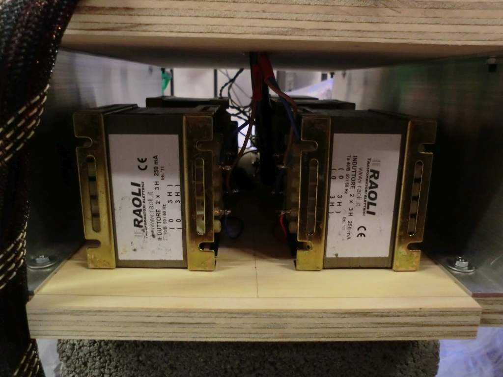
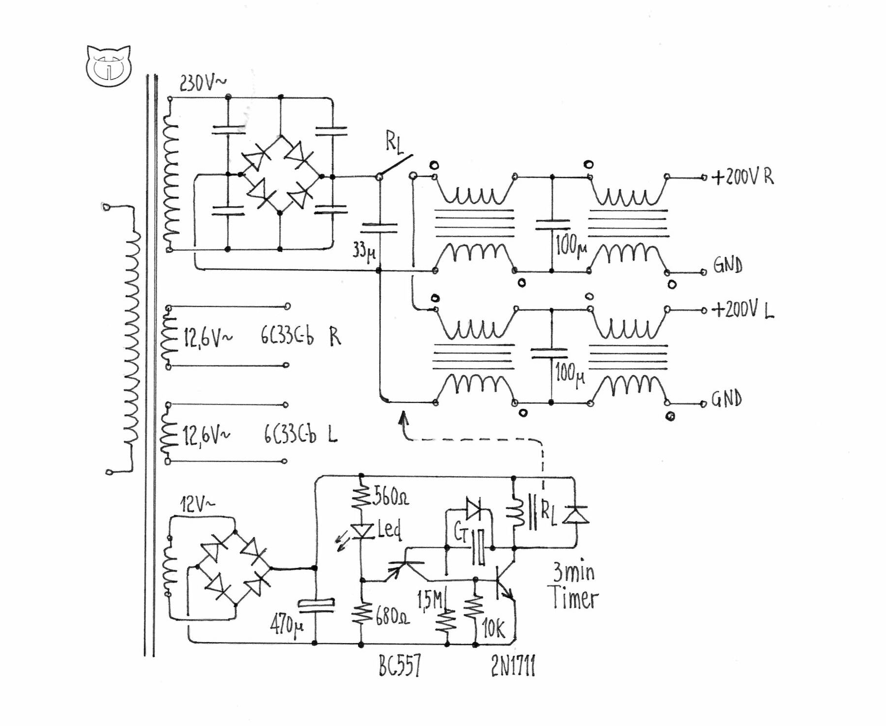
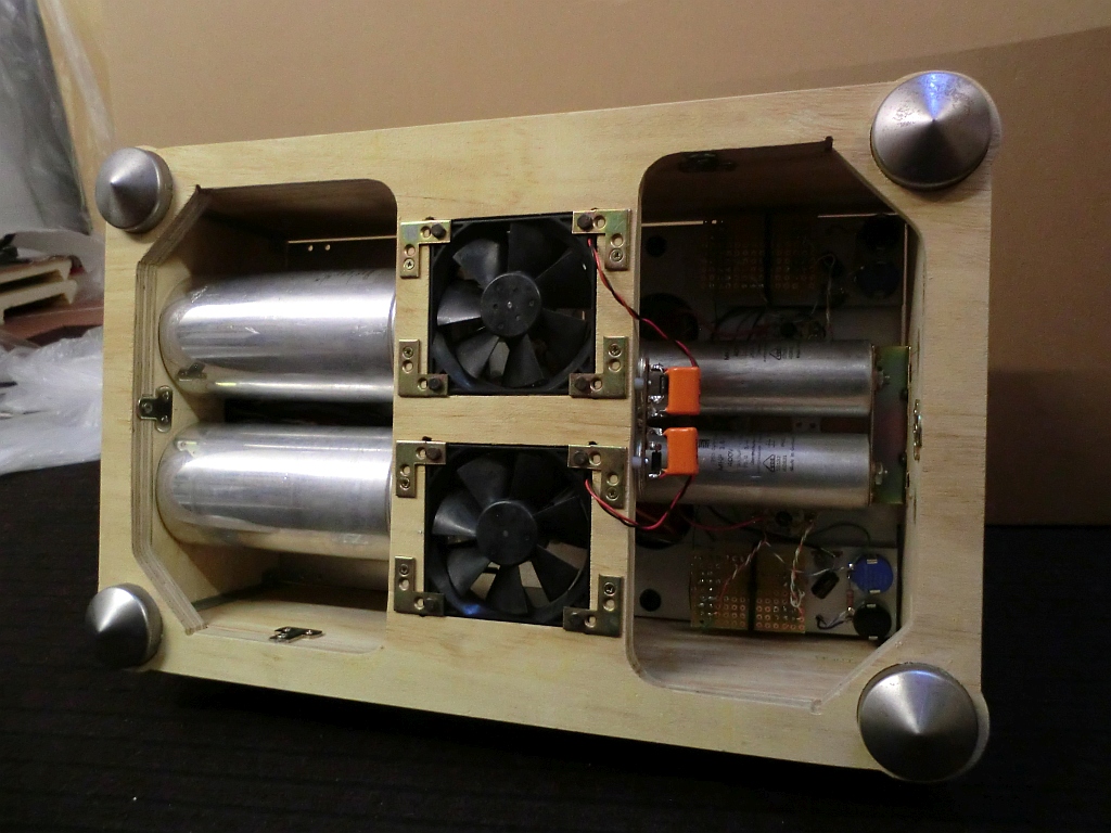
In the power supply, I adopt a vacuum tube rectifier ( 5V4G ) for 6SN7GT input stage. The first capacitor after 5V4G rectifier MUST be paper in oil type. In the schematic you can see a LCLC type filter for best ripple reduction followed by two other cells LC to separate right, left channel power supply line. Due to high current ( and voltage drop ) of 6C33C-b output stage, vacuum tube rectifier are not recommended. Here a solid state bridge MUR860 600V, 8A ultrafast rectifiers is for me the best choice. After the first 33 uF MKP capacitor, the power supply is splitted in two sections for Left and Right channel. Here I use a LCLC filter with two double 3H chokes per channel, and MKP capacitors to obtain a very low residual ripple. As you can see in the photos, the power supply chassis is made in two levels: in the downside is put the 6C33C-b part ( HT plus filament transformer ) while the upper level houses the 6SN7 power supply and timer. Please note in the 6C33C-b power supply the double choke wound in same core to improve inductance up to 12H and ripple rejection ( note the phase point in the positive and negative leg ).
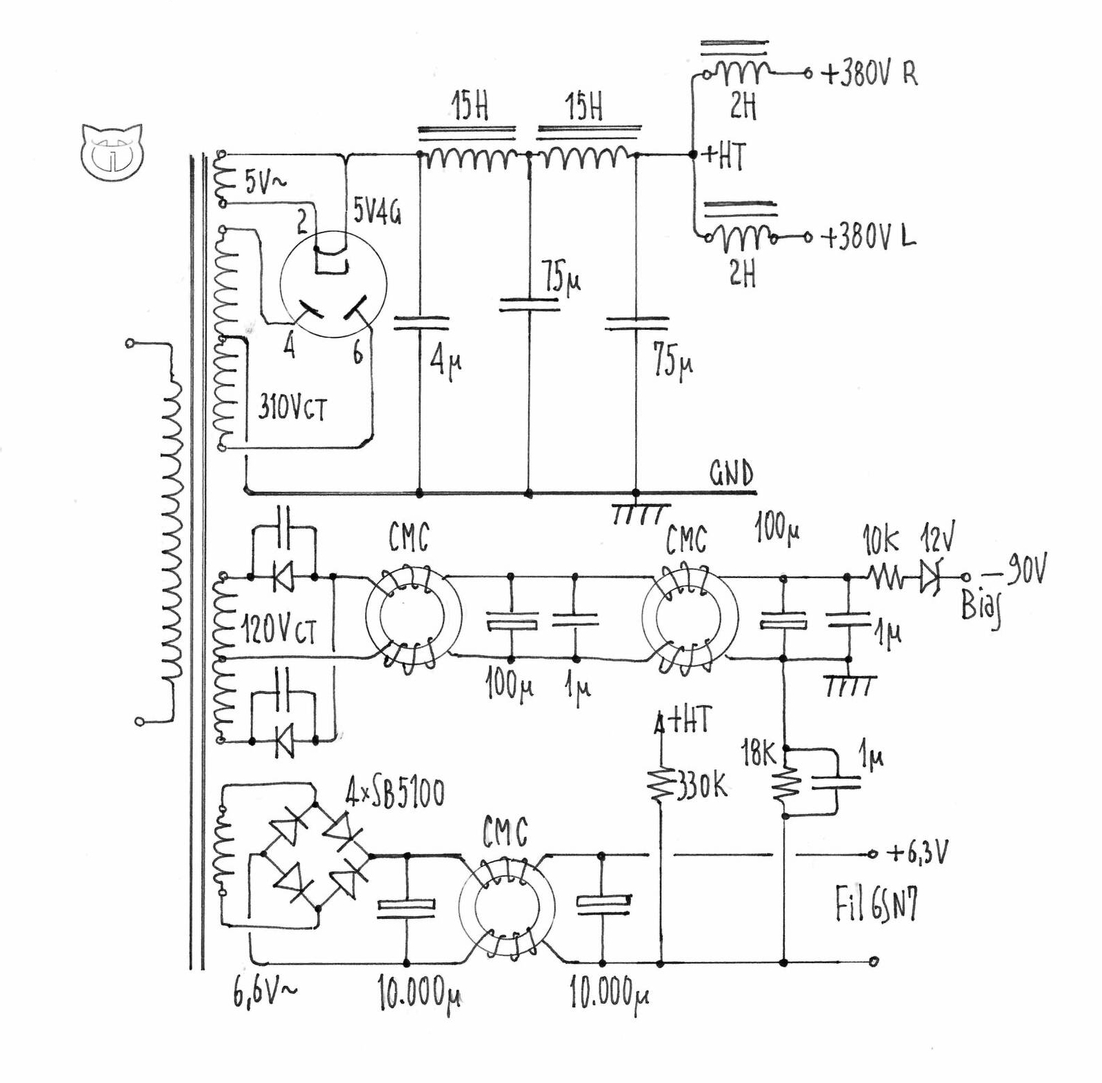
Bypass MUR 860 diodes with 1,5-2,2 nF-1000V Silver Mica or Ceramic capacitors. In general I like fixed bias for tubes in each stage but here in the 6C33C-b stage is indispensable to avoid matched tubes, high dissipation in the cathode resistors, and a higher anode voltage for compensate the voltage drop in these resistors. The 6C33C-b has huge inconsistency of parameters when it is new, so it is very difficult to measure the parameters. The reason that these tubes show varying characteristics is not because of bad quality manufacturing but is that as the 6C33C-b has very high transconductance the internal spacing between the electrodes is very small and therefore even a tiny difference in the spacing will have a big effect on parameters. It’s useful to make bias supply available from minus 50V to minus 120V. Biasing resistor that goes to the 6C33C-b grid should be the best possible quality and has value less than 100K. For grid stopper resistors use carbon composite type Allen-Bradley or similar and Blackgate or Elna SilmicII capacitors in the negative side of bias. Although the 6C33C-b marked for 60W plate dissipation, I recommended a plate dissipation 40 W for a full tube ( both halves paralled ). To protect the ceramic tube sockets and maximize air exchange, the sockets are mounted floating on stand-offs, and a forced ventilation with two fan at downside of chassis put in axis of power tube help to dissipate heat. These two 12 V fans are powered at 6V DC to reduce speed and noise.
6C33C-b burn in: when you take as brand new tube, heat its filaments up for 2 minutes and start the amp with 20mA on plate. In 10-15 minutes the plate current will rise to 150mA – let it be this way. Burn the tune for another 3-6 hours with 100mA-150mA and then consider it ready to be use at full power.
This amplifier employs a relay-controlled timer to allow the tubes time to warm up and stabilize. These circuits provide a 3-minute delay to pre-warm the output tubes. The capacitor Ct set the delay time ( for 3 min, 100uF is the correct value ).
![]()
Except for the negative bias circuit and the time delay put in a common board, I adopt the point to point (PTP) wiring technique. All circuit connections are made directly between components, using the leads of those components themselves and very little wire. In the PTP amp, the signal path is usually as short as possible—which, when done right, can help minimize interference and noise in the circuit and the circuit flows logically from input to output. The circuit itself, therefore, tends to look very much like the schematic diagram from which it is built.
When we “measure the bias” we actually measure the voltage drop across the cathode resistor of that tube. In the output stage, check and adjust the bias voltage every 10 hours during the next 50 hours break-in with a millivolmeter across a 1ohm 1% resistor ( TP2 ). I recommend keeping bias voltage at 200mV DC ( 200mA in the 6C33C-b ) for best accordance tube life/output power. In the input/driver stage 150mV across 10 ohm resistor is the correct bias value ( 15 mA in the 6SN7GT group ). Both bias measurement resistors are put in short by push button normally closed P1 and P2: these resistors are insert in the circuit only when we test bias.
About listening experience I found this amplifier is a quite spectacular full bandwidth ‘muscle’ triode amps. Dynamic attacks are in the first class amplifiers but also delicate nuances like female voices or violin strings are played as the best 2A3 tubes. If midrange is true direct-heated triode without the excess bloom, bass has the speed, grip, tremendous impact and shocking growl that lives somewhere between a good transistor amp for transients and control and the saturation of a high-power p/p valve machine. Iron and velvet: This amp sings freely and let’s go with a flourish.

Very good details and development aout the 6C33 SE amplifier.
Many thanks
I am interested in this unit. Can u give me a cost
Hoping for a reply
tempting without being able to have
Hi There,
After some help in biasing my monoblocks.
Please get back to me if possible,
Thank you
Hi,
I’m gonna build your 6c33 single ended, in the 6sn7 what was the cathode tension that you think? I’m gonna put auto bias with a resistor and a cap
Thanks